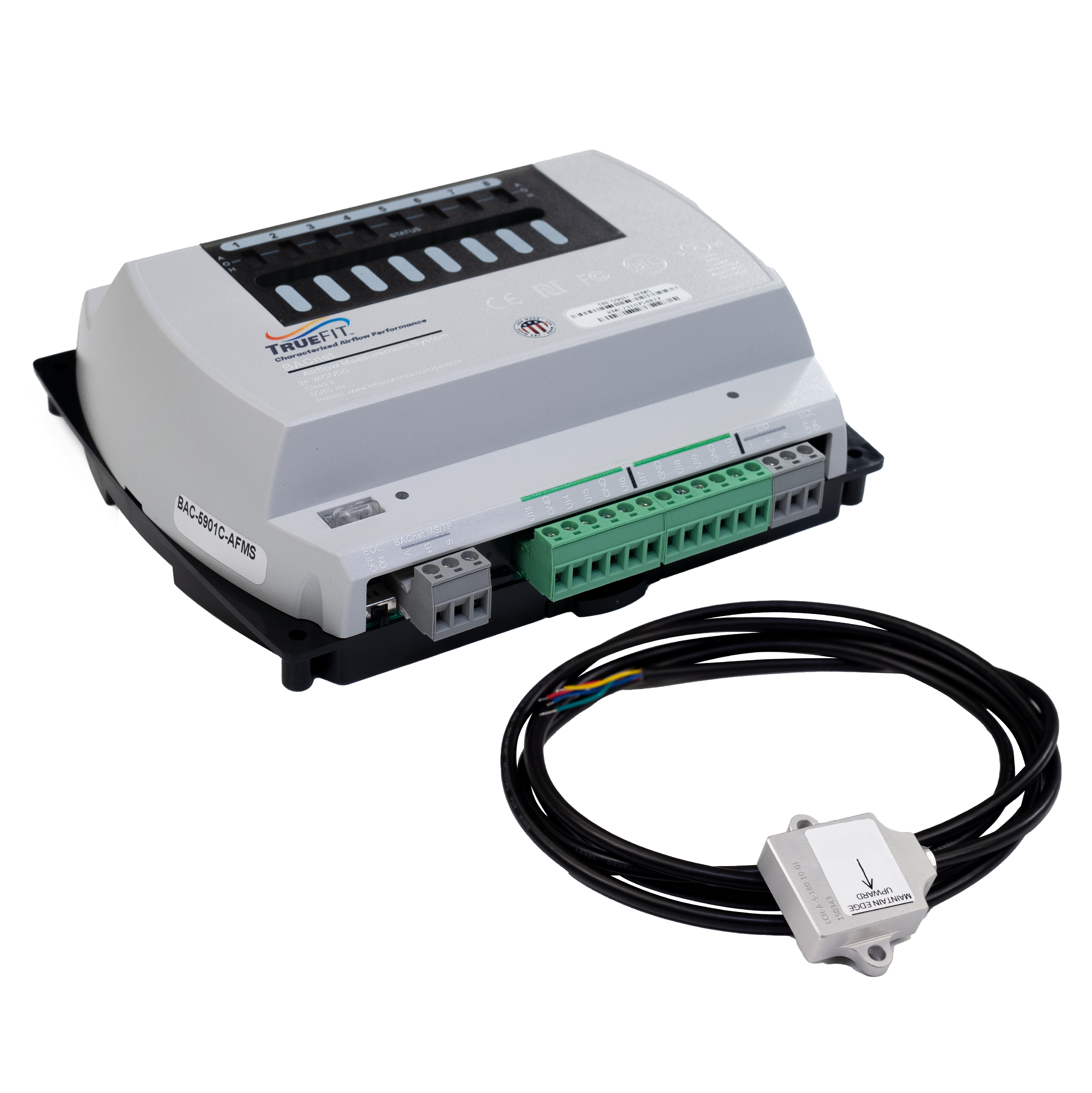
TRF-5901C-AFMS | Controller: TrueFit Airflow Measurement System, BACnet AAC, Clock, MSTP
Sign in with a qualified account to view pricing or
learn how to buy KMC products.
OVERVIEW | TrueFit AFMS: Pressure Assist and Standard, GP, MSTP
Description
The TrueFit™ Airflow Measurement System (AFMS) reliably provides accurate outside, return, and supply airflow data for monitoring and control. The system delivers accurate, repeatable results on any type of equipment, without the traditionally expected mechanical limitations, performance issues, or ongoing maintenance issues.
The system consists of the following components, installed on an AHU, RTU, or unit ventilator:
- One controller with airflow measurement programming
- One inclinometer (included with the controller) mounted on a horizontal outside or return air damper blade
- If only vertical damper blades, one HLO-1050 Linkage Kit
- At least two flow pickup tubes installed in the supply air duct, or on the fan inlet
- If a TRF-5901C(E)-AFMS is used, one pressure transducer
- If pressure assist measurements are needed (for units with changing pressure in mixed and/or return air sections, or for units with more than one outside air damper), one additional pressure transducer, connected to two additional flow pickup tubes that are mounted on both sides of either the outside air damper or return air damper.
- Three temperature sensors, for outside, mixed, and return air
- One proportional actuator mounted on the damper shaft
(See the TrueFit AFMS Selection Guide for details.)
The system measures outside and return airflow by characterizing damper performance. The AFMS controller’s programming generates a characterization curve using a Learning Mode sequence. It does this by leveraging the relationship between the inclinometer and a mixed air equation from ASHRAE Standard 111. During Learning Mode, the damper is positioned at several points (gradually increased percentages of open, as measured by the inclinometer). At each point, the airflow and temperature readings are allowed to stabilize before being sampled and averaged. The controller uses those readings and the mixed air equation to calculate the fraction of OA/RA at each position. The results are recorded in a damper characterization table. Thereafter, the sensors are no longer needed to measure the airflow, but are left in place for fault detection and later re-calibration.
Features
- Measurements of outside, return, and supply airflow accurate within three percent
- Sensor and system fault detection for Title 24 compliance
- Installs without restrictions of installation location
- Reduced system maintenance requirements
- AHU, RTU, and unit ventilator applications
- Applicable to both VAV and CAV systems
- Learning Mode started locally or remotely
- Four control modes: outside airflow, mixed air temperature, damper position, and pass through
- Interoperability with any BACnet open automation system
Specifications
| Analog Inputs | 2 |
|---|---|
| Application | Unit Ventilator, AHU, RTU |
| BACnet Profile | Advanced Application Controller |
| Brand | KMC Controls |
| Connectivity | MS/TP |
| Universal Inputs | 8 |
| Universal Outputs | 8 |
 Cart
Cart

